Tuesday 20 May 2014


Friday 16 May 2014


Saturday 3 May 2014

GH https://www.dropbox.com/s/3pvnvqnd30rudlt/Task3TEST.gh
RN https://www.dropbox.com/s/6w7fomngr9o7tne/Task3Final.3dm
The initial idea of the waffle script was to keep the cutting as a 2D element since laser cutting is not done in 3D. This way, if I use it in the future for more complicated models the computer wont lag so much as it calculates the changes. I found that in task2, it took so long for the changes to be implemented once the model became somewhat complex and this was a pain. I will have to go back and change the scrip if I desire the above effect.


I had no idea how to lay the sections out so I used Victor Leung's definition shared on grasshopper3D.com and adapted to this script.

Wednesday 16 April 2014
week//five

so a very very late submission&post of the task due before we split for the break. i was no where near close to finished and had not reached the goal i intended to - in fact wasted time trying to build a pointless definition that wouldn't have worked out, come 3D printing. i needed to review what needed to be done and the following is the out come.
grasshopper file found here. *NB Turn on the lofts and create a point next to the bounding box, and apply it to the attractor point.
part1 geometry
the first step allowed me to figure out the geometry i was after and apply thickness and some extra parameters that varied its height, fillet and rotation, which i hoped the attractor point would control later on. i initially thought i can use the completed geometry and apply them onto a surface but this failed (or i'm simply not sure how to go about achieving it) forcing me to go back and remodel the geometry from a tri grid. this wasn't much of an issue as i could mostly copy the logic almost as is, to get the geometry back up with the same properties.
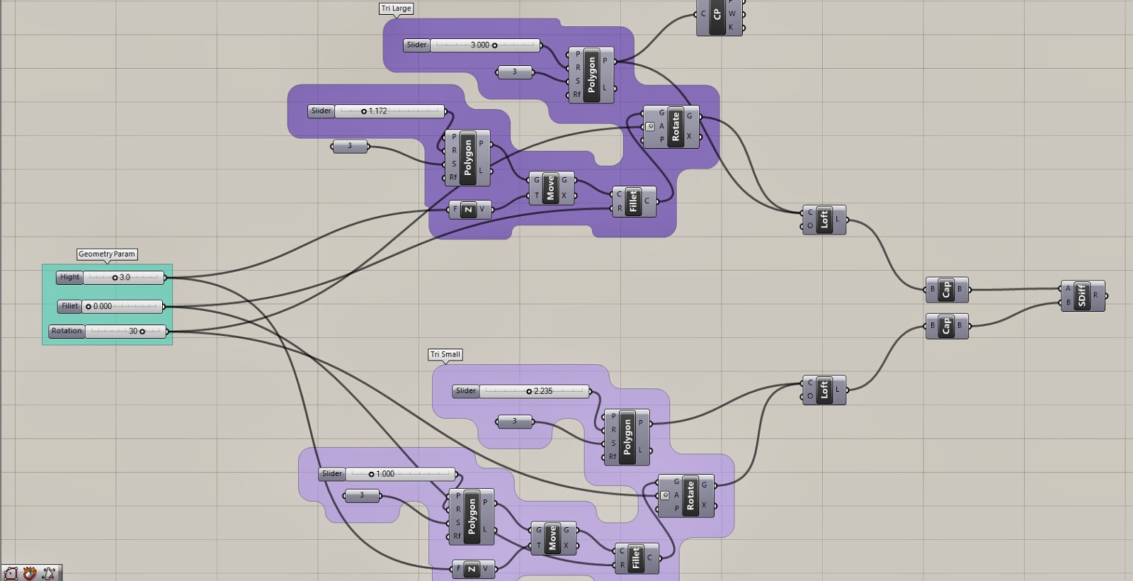 all i did here was start with a polygon with a segment definition of 3 for a triangle. copied the definition to make a smaller triangle and loft the two, whilst offsetting them to achieve thickness. in the process i have dragged out buttons to control the parameters for height, it's fillet (from triangle to circular form) and the rotation (to 'skew' the lofted surface. in retrospect i should have figured one thing out - as the fillet increases, the rotation of the triangle disappears since the top portion turns into a circle.

part2 grid+geometry+attractor pt+morph


Saturday 22 March 2014
week//three

unaware of the fact that the requirements for t-1 was to produce a simple solid, i had searched tutorials outlining the ability to produce and apply organic forms only to find that it is far too complex to achieve such scripts at this stage. the solution was to find out how to produce more simple parametric geometry and apply this to a surface which will form the boundary of the chosen letter.
what seemed to be a sound choice was a simple truss system - patterns to be made of triangles and hopefully easy to manipulate. the idea was to produce a portion of this component and simply apply it onto the surface of a the letter 'v' and hope for grasshopper to calculate the rest. the result should be similar to a tiling effect where the pattern backs onto each other creating a continuous form.
Files Found here:
https://www.dropbox.com/s/axt7wo996qcs0h0/virili_sean_task1.gh
https://www.dropbox.com/s/oflivfdf0gvymir/virili_sean_task1.3dm
 |
| fig1: producing a segment of a truss |
 |
| fig2: failed script |
i begun by creating a surface in g/h with 4 points, setting its planes to draw polylines along the desired axis. you can see in the image below that the surface from 4pointSurface tool needs inputs first to begin the calculations. (the wires are orange as this script is disabled) the remaining script it basically identical to the current version and will not require further discussion.
 |
| fig3: complete script including surface application to geometry (letter V) |
part1 production
i// to avoid the error in fig 1, a surface was drawn in rhino with SrfFPt tool using 4 points, then brought into g/h and applied to a surface parameter. this was then exploded in order to allow for point selection where the list items tool was used to specify the coordinates of the surface.
 |
| fig4. part 1 truss script |
iii// the polylines are then offset with a slider bar to control the width of the inner frame. this is then linked to a fillet tool to round off the edges for a smooth aesthetic.
iv// to acquire data for the area concerning the framework requires a subtraction of the inner geometry from the bounding box. the boundary box holding the lines for the geometry is saved as a curve parameter and then given a surface with the planarSrf tool. this process is repeated for the offset geometry and then plugged into region difference tool. this process required some trial and error as the tutorial was demonstrated on an older version of rhino, causing problems with the scripts. the tutorial used solid difference instead, and did not seem to require a planar plug in at the end of the script to give a surface to the outlines of the subtraction.
 |
| fig5: process of trust production |
 |
| fig6: complete truss |
 |
| fig7: part 2 apply to surface |
i// define the geometry of the letter V by drawing a curve in rhino and importing it into g/h's curve parameter. offsetting it to achieve thickness.
ii// divisions were made along the curve to draw reference points
iii// a surface was then applied to the bounding curves of the letter with surface grid tool, which was then divided using divide domain tool.
iv// finally the script is plugged into isotrim before linked into the truss system. the script did not seem to function without this parameter as the surface param from part 1 was unable to read the domains directly from the surface grid. what the isotrim seems to do is apply a secondary surface for the parametric object, in this case the truss system, to function on. the isotrim can also be used on 3d surfaces that have been lofted, and so forth.
 |
| fig8: process of surface application |
 |
| fig9: complete letter |
possible application for a 3D printed version of the completed script was also made. almost all the logic used was identical, however applied to a lofted surface which was made in rhino instead. the script was made and then mirrored to complete the final form.
fig10: cut letter

 |
| fig12: script for a lofted 3D letter |
 |
| fig13: product of a 3D letter with the above script |
Subscribe to:
Posts (Atom)